DRAWING ----> SCIENCE ----> MECHANICAL ENGINEERING
Based on my own experience in architecture, urban design and engineering fields, I am very interested to use this collaboration opportunity to examine the role of visual communication in mechanical engineering field. My aim is to expand my knowledge in science (physics/mathematics in mechanical engineering) and its relationship with drawing; and also, to be able to compare research methods in two different fields of art and engineering specifically at a doctorate level.
In this research, I pursued three different approaches to understand the role of drawing through a PhD candidate in the field of Mechanical Engineering:
In this research, I pursued three different approaches to understand the role of drawing through a PhD candidate in the field of Mechanical Engineering:
- Drawing as an application for a PhD student in engineering
- Mechanical engineering’s programming application to draw with
- Drawing on a material as a result of a PhD student’s laboratory work
|
|
|
|
|
|
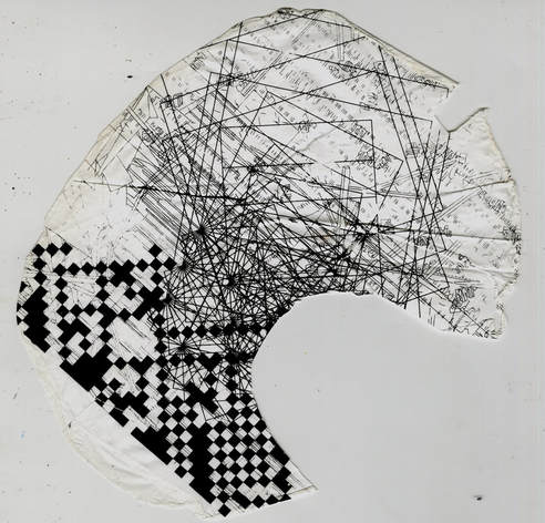
The second investigation was the idea of coding in creation of a drawing and also analyzing my drawing by using different computational techniques and algorithms. There is coding software (MATLAB) which is one of the most commonly used software packages in mechanical engineering. Therefore, working with a PhD student in this field would be very helpful to learn it better. This software can provide the possibility of analysing the drawings based on my narrative. I will be able to write a function or an equation which follows my art practice concept to run the analysis on my drawings. I can then generate a new set of drawings based on the initial input.
Monte-Carlo:
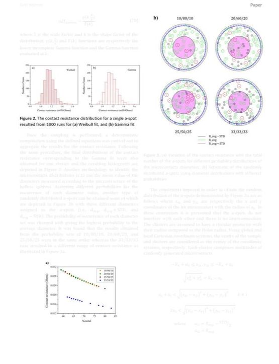
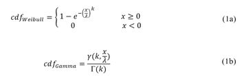
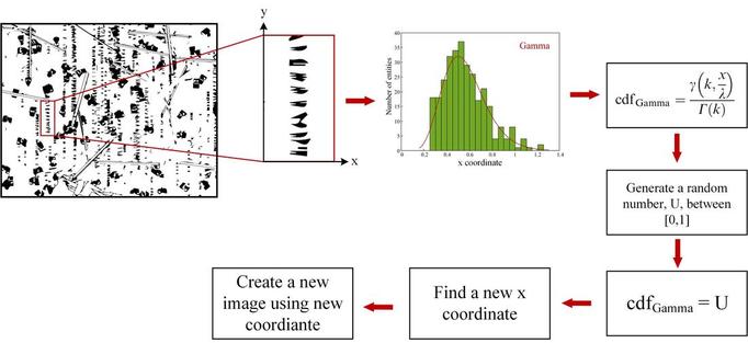
An example of a simulation technique that I used in MATLAB to perform my analysis is called the Monte-Carlo technique. A physical system that can be described through a probability distribution function (pdf) can be simulated using this technique by randomly sampling from the pdf’s of the input variables. Performing further calculations, one can describe the evolution of the system and obtain its final output probability distribution. Using the coordinates of the points in each section of a drawing as the defined domain of possible inputs, the new points inputs can be randomly generated by inversely sampling from each of the pdf’s. This entails sampling a random number ε from the interval of U[0,1] and equating the randomly picked number with the cumulative distribution function (cdf) of the original points (F(x)=ε). Finally, the sampled value x can be found by inverting the cdf as x=F-1(ε). The cdfs corresponding to a Weibull distribution and a Gamma distribution are as follows:
Where λ is the scale factor and k is the shape factor of the distribution. γ(k,x/λ) and Γ(k) functions are respectively the lower incomplete Gamma function and the Gamma function evaluated at k. By using this method, different sets of new drawings can be generated from the original one. Increasing the number of iterations will result in a drawing closer to the original one however generated using a mathematical based technique.
This approach encountered some errors which have not been resolved yet due to lack of time. We could not generate any drawing as an output of my initial drawing. However, by doing more analysis and debugging the code, I believe that those minor issues will be fixed.
Monte-Carlo:
An example of a simulation technique that I used in MATLAB to perform my analysis is called the Monte-Carlo technique. A physical system that can be described through a probability distribution function (pdf) can be simulated using this technique by randomly sampling from the pdf’s of the input variables. Performing further calculations, one can describe the evolution of the system and obtain its final output probability distribution. Using the coordinates of the points in each section of a drawing as the defined domain of possible inputs, the new points inputs can be randomly generated by inversely sampling from each of the pdf’s. This entails sampling a random number ε from the interval of U[0,1] and equating the randomly picked number with the cumulative distribution function (cdf) of the original points (F(x)=ε). Finally, the sampled value x can be found by inverting the cdf as x=F-1(ε). The cdfs corresponding to a Weibull distribution and a Gamma distribution are as follows:
Where λ is the scale factor and k is the shape factor of the distribution. γ(k,x/λ) and Γ(k) functions are respectively the lower incomplete Gamma function and the Gamma function evaluated at k. By using this method, different sets of new drawings can be generated from the original one. Increasing the number of iterations will result in a drawing closer to the original one however generated using a mathematical based technique.
This approach encountered some errors which have not been resolved yet due to lack of time. We could not generate any drawing as an output of my initial drawing. However, by doing more analysis and debugging the code, I believe that those minor issues will be fixed.
The last part was to look at the process of making a fibrous mat in her laboratory as part of her research on smart materials. She used an electrospinning technique to fabricate a polymeric fibrous substrate as elaborated below:
Electrospinning is a facile method to fabricate micro/nanoscale polymeric fibers. In this method, a polymer solution or polymer melt is fed through a spinneret with a specific feeding rate and is exposed to a high voltage (10 to 20 kV). If the applied voltage which results in an external electric field is sufficient, the electrostatic repulsion force counteracts the surface tension of the droplet at the tip of the needle. This contributes to stretching of the droplet and hence reaching a critical point at which a stream of liquid erupts from the surface. The jet of the polymer solution flies towards a grounded collector while the solvent evaporates leading to formation of uniform polymeric fibers with micro/nanoscale diameters. [2]
Material:
The polymer composite fibers were electrospun using mixtures of thermoplastic polyurethane (TPU, Desmopan 385E) and polylactic acid (PLA, 3052D NatureWorks) with varying weight ratios. After evaluating different volatile solvents, dimethylformamide (DMF, Sigma Aldrich) and tetrahydrofuran (THF, Sigma Aldrich) were found to have an optimum performance in both dissolving the polymers and their properties to enhance the electrospinning process. [3]
Method:
A 10% TPU powder solution was created using a 1:1 weight ratio of DMF and THF as solvents. A 20% solution of PLA pellets was made using the same solvent composition. These solutions were then mixed together to make a 15 mL mixture, using a TPU to PLA polymer weight ratio of 100:0, 75:25, 50:50, 25:75, and 0:100. These mixtures were then mixed using a magnetic stirrer for 30 minutes at room temperature, and electrospun using the following parameters: 20kV electrostatic field, 12 cm collecting distance, 40oC temperature, 25 % relative humidity, and 3 ml/h pumping rate. The fibers were collected onto a static current collector and cut into thin films.
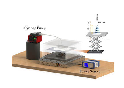
Strain sensor fabrication depicting: the electrospinning.
|
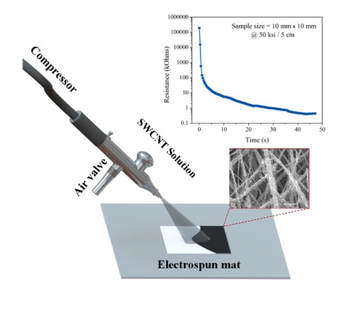
Strain sensor fabrication depicting: spray coating procedures.
|
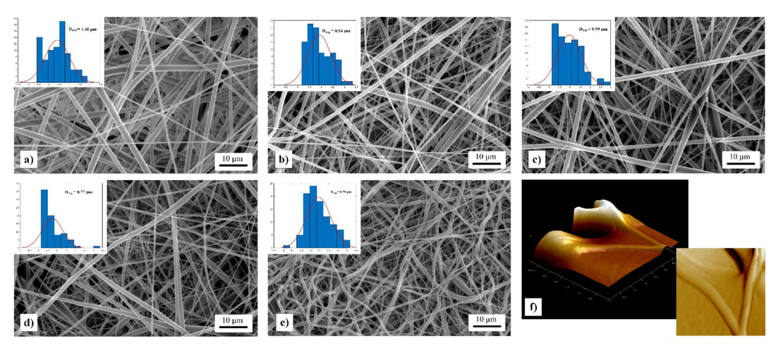
SEM images of electrospun TPU/PLA fiber mats with varying TPU:PLA weight ratio % as a) 0:100, b) 25:75, c) 50:50, d) 75:25, and e) 100:0.
Nazanin Khalili's publication, (University of Toronto): reference of fibres' above illustrations
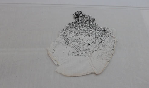
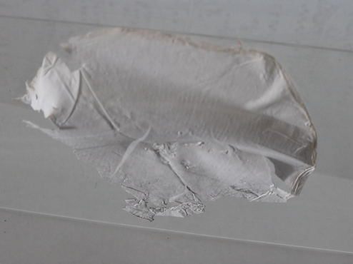
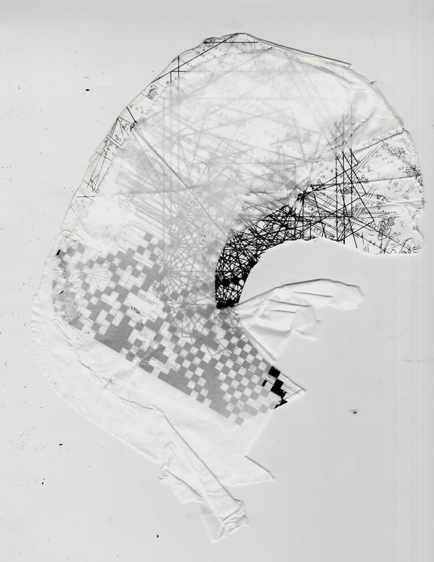
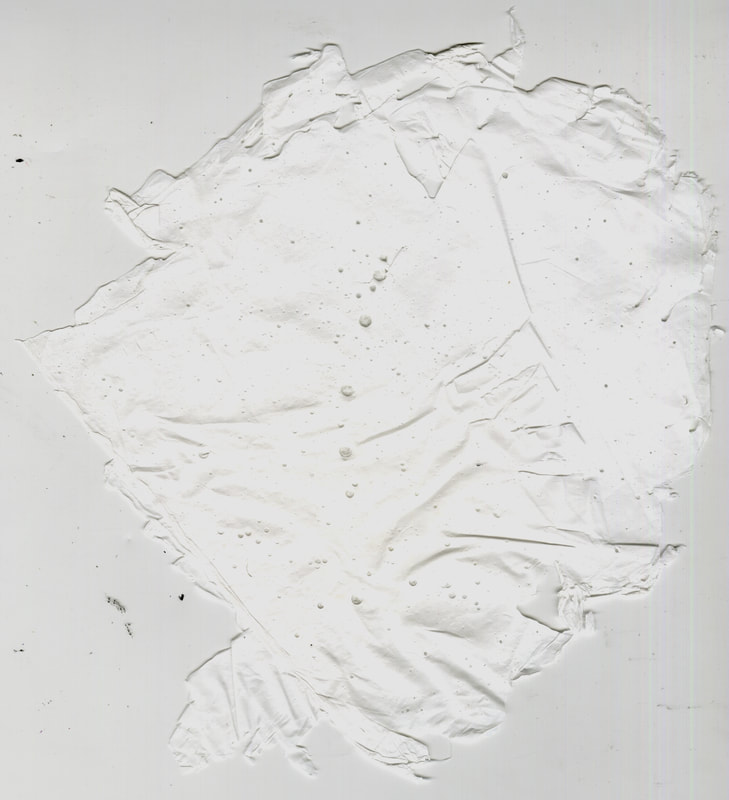
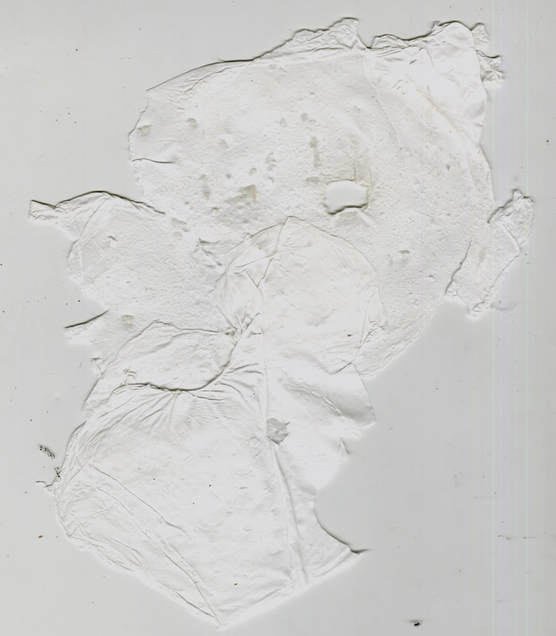
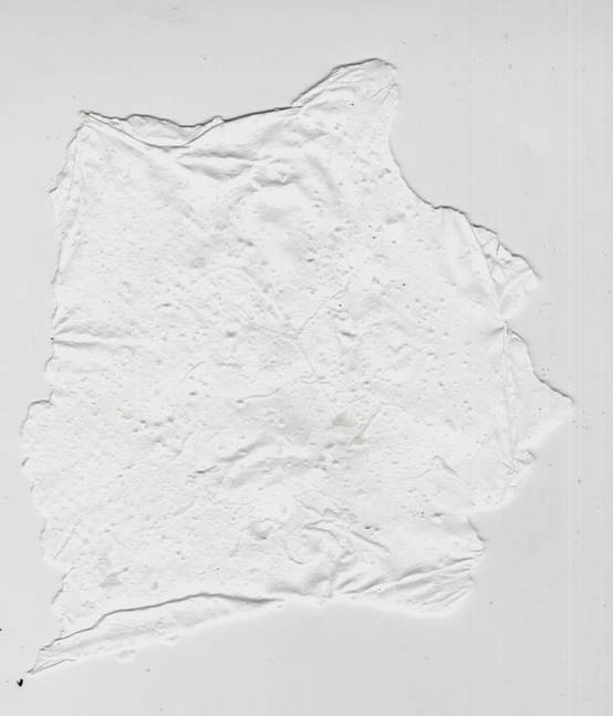
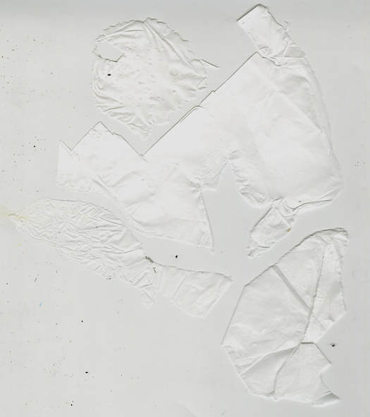
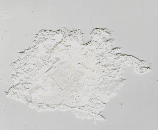
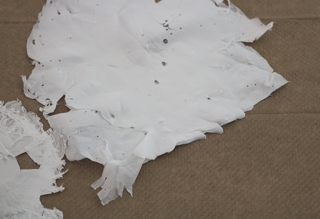
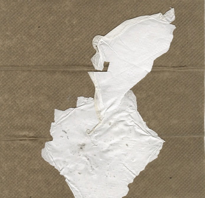
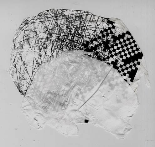
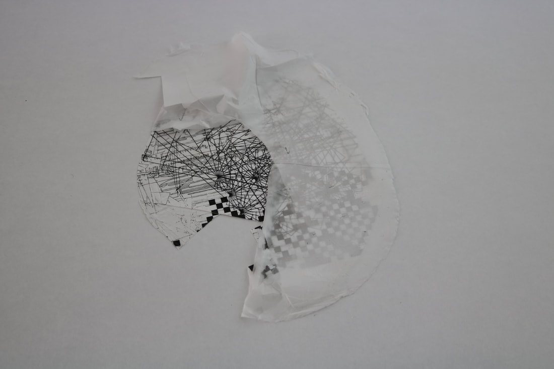
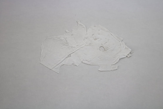
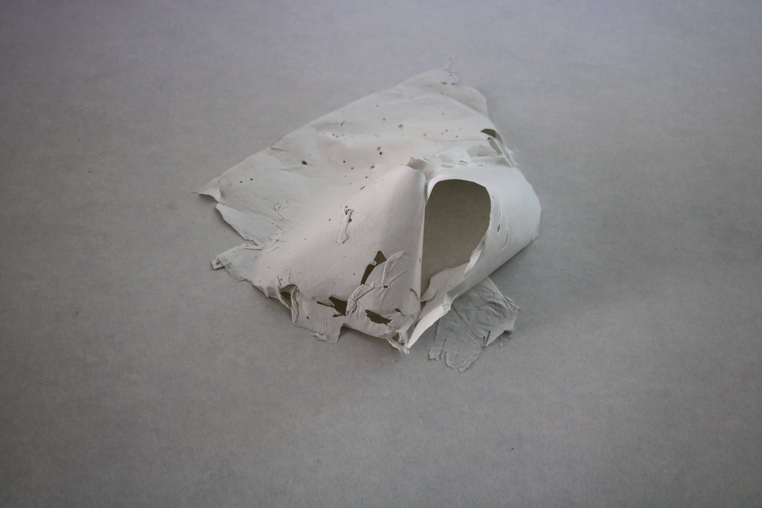
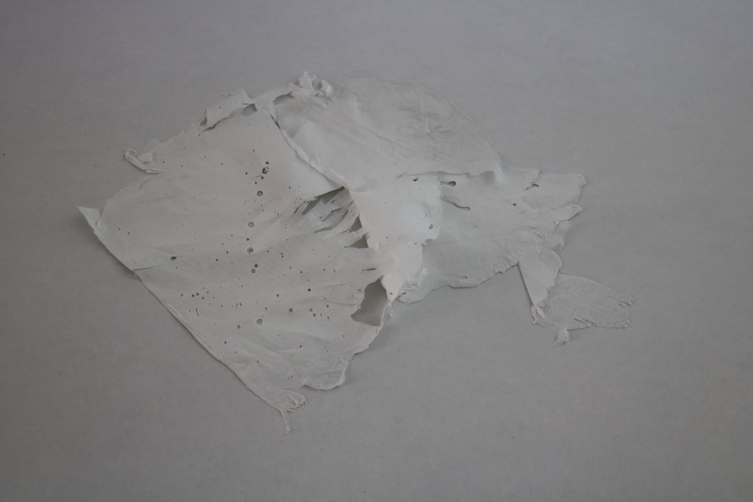
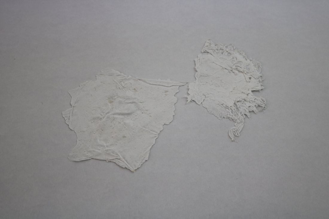
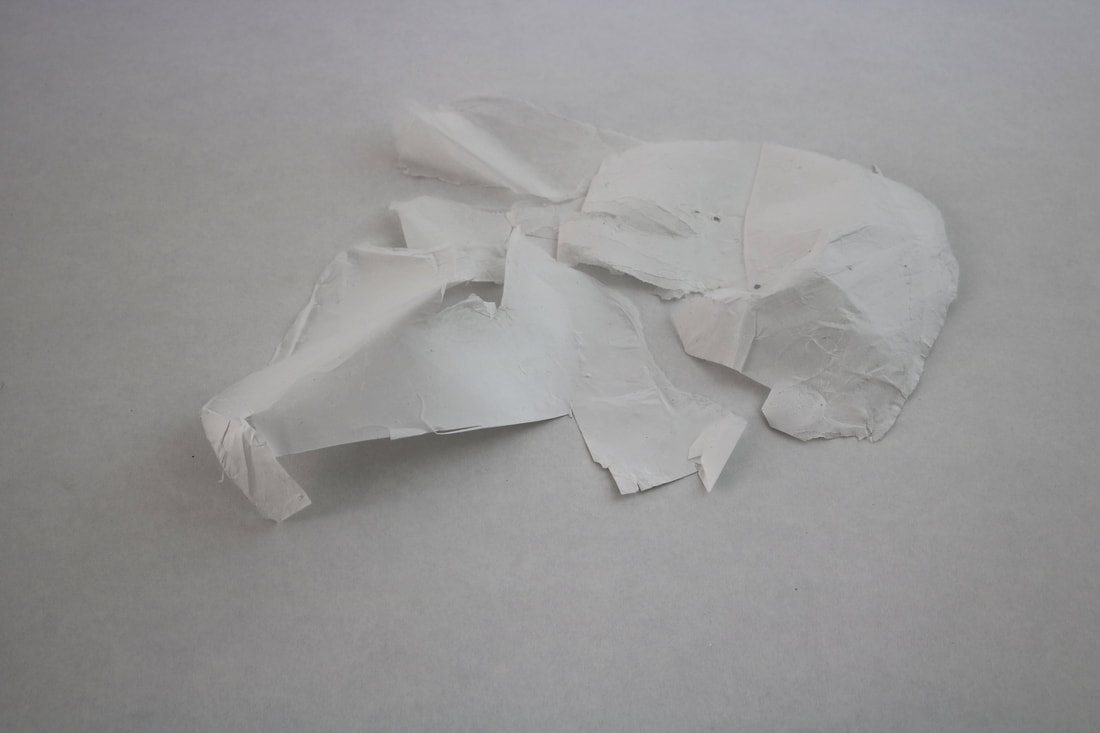
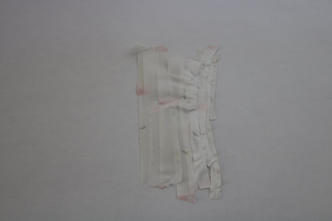
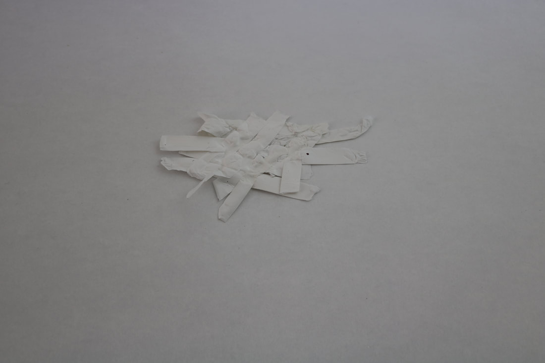
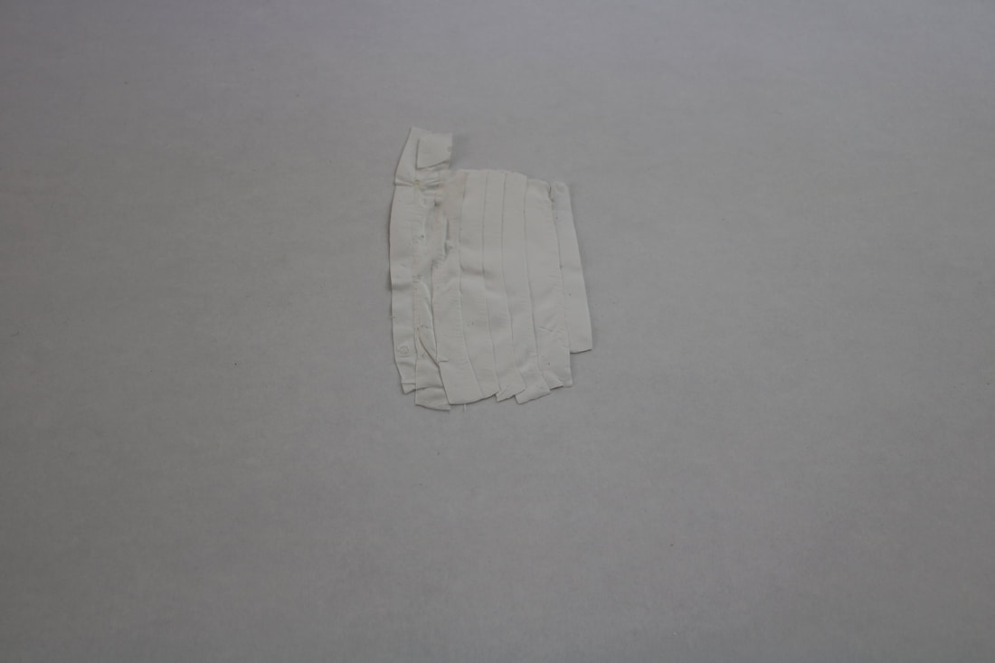
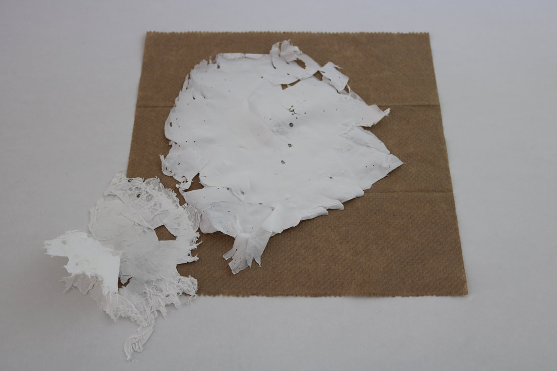
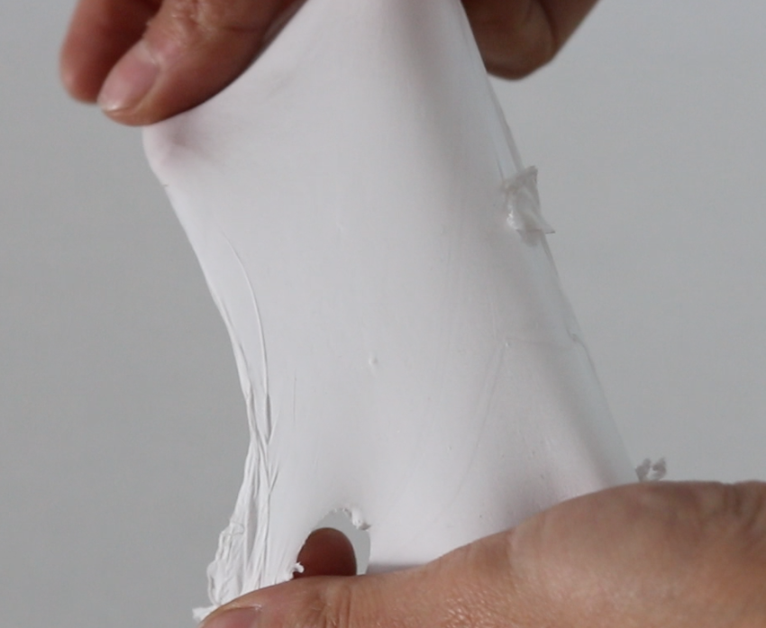
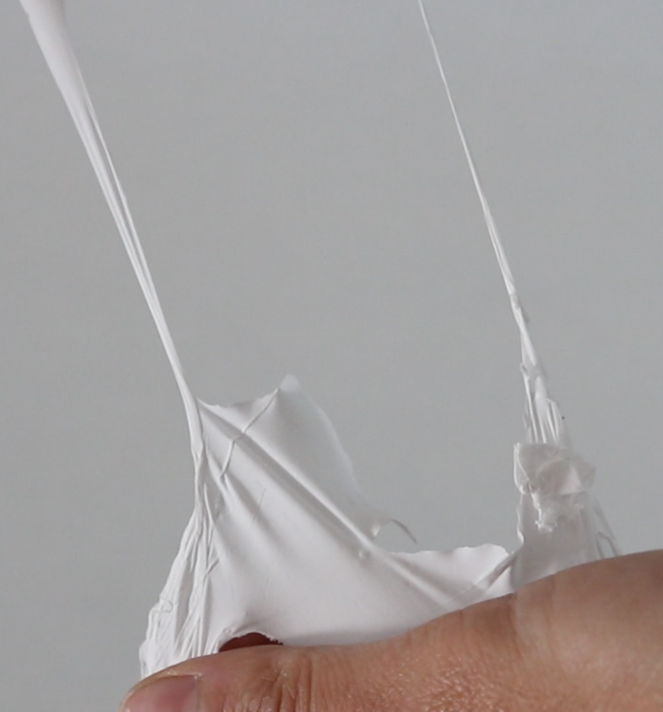
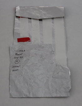
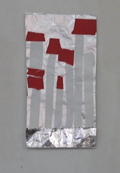
As a result, we have different types of fibers with various characteristics such as various textures from very smooth to very rough surfaces, very thick to very thin and transparent films, fibers with varying absorbing capacity of the marks after applying pressure and also films with different ranges of flexibility in the stretch mode. In order to be able to analyze this process to understand the possibilities of using this new product as a new material to draw on, I investigated these fibers to do further experiment such as:
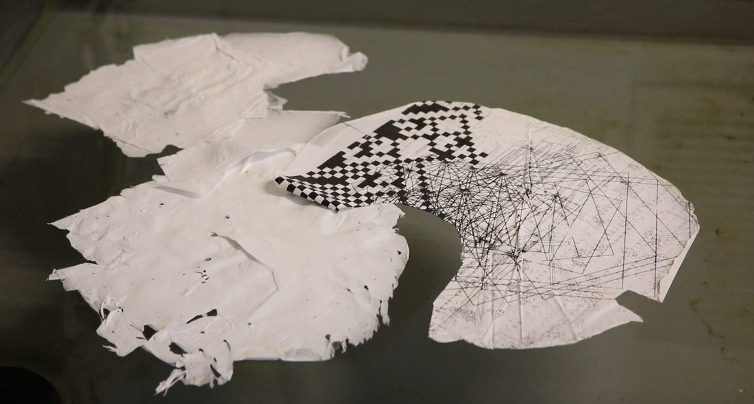
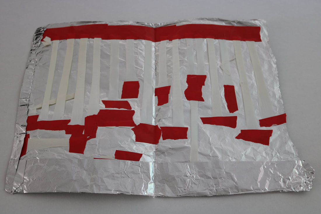
- Screen printing one of my drawings on a fibrous mat as a surface
- Using the concept of layering due to the variation of transparency of these films
- Using them as a surface on which I can make a mark by pressing different textures onto them
- Investigating the potential of creating a new composition by stitching and gluing them together
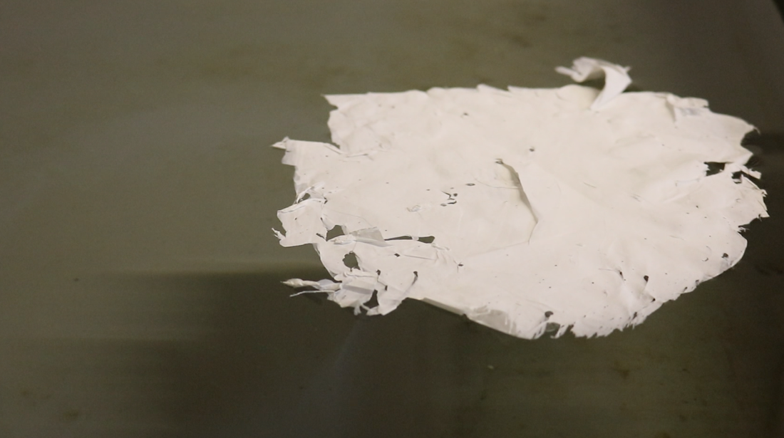
- Examining the idea of floatation on water
|
|
Conclusion
In conclusion, I would like to count this path of collaboration with my sister as a learning process for two professionals in two different fields. I was able to differentiate between the thinking method in her research and mine not only as two different individuals but also from two different viewpoints of art and engineering. Based on my findings, the usage of drawing in her field is a part of the result delivery subsequent to the mathematical, physical, and technical laboratory experiments.
Although I failed in my second approach to produce tangible results from the Monte Carlo using MATLAB and could not generate the analysis I was wishing to test on my drawings, I will definitely continue to work on this concept and try to solve the problem using the analysis method.
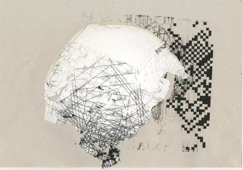
The result of the third step was very interesting since I was able to use a new material (based on my scope of experiments) and create totally new drawings by incorporating the new possibilities. This process of creation gave me the opportunity to question the boundaries in my drawing process and learn to think in a wider context when I want to start a new research.
References:
Although I failed in my second approach to produce tangible results from the Monte Carlo using MATLAB and could not generate the analysis I was wishing to test on my drawings, I will definitely continue to work on this concept and try to solve the problem using the analysis method.
The result of the third step was very interesting since I was able to use a new material (based on my scope of experiments) and create totally new drawings by incorporating the new possibilities. This process of creation gave me the opportunity to question the boundaries in my drawing process and learn to think in a wider context when I want to start a new research.
References:
- Khalili, N., H. E. Naguib, and R. H. Kwon. "A constriction resistance model of conjugated polymer based piezoresistive sensors for electronic skin applications." Soft matter 12.18 (2016): 4180-4189.
- Doshi, Jayesh, and Darrell H. Reneker. "Electrospinning process and applications of electrospun fibers." Industry Applications Society Annual Meeting, 1993., Conference Record of the 1993 IEEE. IEEE, 1993.
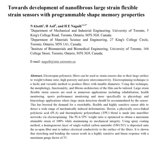
- Khalili, N., H. Asif, and H. E. Naguib. "Towards development of nanofibrous large strain flexible strain sensors with programmable shape memory properties." Smart Materials and Structures 27.5 (2018): 055002.
| khalili_sepideh_learner_agreement_unit_3.pdf |
| khalili_sepideh_unit_3_presentation.pdf |
| khalili_sepideh_unit_3_practice_in_context.pdf |
